My favorite sportscaster John Sterling, who calls for the New York Yankees. Tune in to 880 WCBS any evening in the summer and fall (esp during MLB playoffs). Real entertainment.
If John had been in the ham shack this morning, making the play-by-play call while I worked DX #260, ZL7/N7OU Chatham Island at my sunrise on 40 CW, he would have uttered those words!
Yes, I did it with 100 watts and my 43 foot vertical antenna.
Of course, it helps that N7OU is a SUPERB operator with terrific hearing.
But give me some credit; the only reason I was able to see his signal and copy him was because of my FlexRadio 3000. How sweet it is/was. Not a lot of folks calling him, and the 43 foot antenna is really superb on 40 meters.
OK, so what DX is next? Bring it, Southeast Asia! 9V1, 9M2, and DU - you are next.
73 and good DX
Monday, September 28, 2009
Thursday, September 24, 2009
If one is good, two must be TWICE as good
Readers are able to discern my obsessions with antennas and DX. It's my drug of choice, thank you very much. No booze, no drugs, no tobacco. Just antennas and DX. I can't ever be satisfied. Just like Michelle Pfeiffer said in her role as Elivra Hancock in the move SCARFACE, "Nothing exeeds like excess." Here's another blogger who captures my thougths well.
Back to my obsession: antennas and DX. When I get to the new QTH, I will be cooking with gas! I plan to bust up some serious pileups after October with my plans.
I did some more simulations for the new QTH for 20 meters, since sunspots are not going to improve soon enough to get me to where I need to be on 15 and 10 for long haul DX.
Here's what I have concluded for 20 meters at the new QTH:
- I will put up two 20 meter hex yagis - one at 32 feet and one at 64 feet
- I will feed the two yagis in phase
- Instead of using a tower, I will use a rope suspension system. I will raise the two antennas and suspend them from a cross-rope at 70 feet. The ropes will use a pulley to connect them at the T junction.
- I will use a pneumatic tennis ball launcher to set up the ropes
Take a look at the NEC pattern here: blue is what I had at the old QTH for a single hex at 32 feet, green is what I had planned with a single hex at 64 feet, and black is the two hexes fed in phase. YOWZA!
In the meantime, here at the old QTH, I heard 9M2CNC on 20 CW on the bobtail antenna. Q3 copy. I was not able to work him. But this is important: it's the first time I have EVER heard a 9M station in my 30+ years of hamming. And it's the first time in a long time that I heard SE Asia. Granted it is prime propagation time with the autumnal equinox cycle, but with our conditions in the doldrums this is a reflection upon the effectiveness of the bobtail. Not quite enough to get INTO SE Asia, but a LOT better than my other antennas.
73 and good DX
Thursday, September 17, 2009
The sounds of DX
Autumnal equinox, DX fans. Symmetrical arrangement of the sun, north versus south of the equator. Happens twice a year. Good time for DX.
To borrow from Robert Duvall as Colonel Kilgore from Apocalypse Now and his quote,
"I love the sound of signals coming in long-path or with polar flutter in the morning. It reminds me of...DX IS"
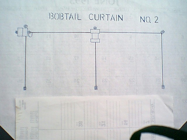
So back to my dilemma of achieving low angle radiation in the direction of SE Asia, I am experimenting with a Bobtail antenna. It's an arrangement of wire that acts as if there are three vertical quarter-wave antennas in phase. Radiation direction maximum is broadside, at low angles (19 degrees).
MFJ has an explanation on their website with some interesting guidance on additional performance enhancements, although the gain claims are (in my opinion) exaggerated.
K3KY has an excellent discussion around the design and considerations for ground.
N8FSC, on his website, has an excellent description of the antenna:
To borrow from Robert Duvall as Colonel Kilgore from Apocalypse Now and his quote,
"I love the sound of signals coming in long-path or with polar flutter in the morning. It reminds me of...DX IS"
So back to my dilemma of achieving low angle radiation in the direction of SE Asia, I am experimenting with a Bobtail antenna. It's an arrangement of wire that acts as if there are three vertical quarter-wave antennas in phase. Radiation direction maximum is broadside, at low angles (19 degrees).
MFJ has an explanation on their website with some interesting guidance on additional performance enhancements, although the gain claims are (in my opinion) exaggerated.
K3KY has an excellent discussion around the design and considerations for ground.
N8FSC, on his website, has an excellent description of the antenna:

The antenna system of Fig 62 uses the principles of cophased verticals to produce a broadside, bi-directional pattern providing approximately 5.8 dB of gain over a single element. The antenna performs as three in-phase top-fed vertical radiators approximately 1/4 wavelength in height and spaced approximately 1/2 wavelength. It is most effective for low angel signals and makes an excellent long-distance antenna for either 3.5 or 7 MHz.
The three vertical sections are the actual radiating components, but only the center element is fed directly. The two horizontal parts A, act as phasing lines and contribute very little to the radiation pattern. Because the current in the center element must be divided between the end sections, the current distribution approaches a binomial 1:2:1 ration.
The vertical elements should be as vertical as possible. The height for the horizontal portion should be slightly greater than B, as shown in Fig 62. The tuning network is resonant at the operating frequency. The L/C ration should be fairly low to provide good loading characteristics. As a starting point, a maximum capacitor value of 75 to 150 pF is recommended, and the inductor value is determined by C and the operating frequency. The network is first turned to resonance and then the tap point is adjusted for the best match. A slight readjustment of C may be necessary. A link coil consisting of a few turns can also be used to feed the antenna.
In the picture above, the antenna is fed at the base of the center vertical section. It presents a high impedance...well above 50 ohms. This can be addressed with the components as shown, or a remote coupler like those made by CG corporation or SGC. I already have the CG-3000 on my 43 foot vertical, but don't want to move it over to the Bobtail AND lay down another radial field.
Fortunately, there is another option: the Bobtail can be fed at the top corner of one of the end vertical elements. The impedance here is on the order of 120 ohms with some reactance, easily matched with a tuner in the shack. With low-loss coax like RG-213, even longer runs (like 200 feet of coax in my case), the calculated losses due to SWR on the line are 2.2 dB (I measured my SWR as 2:7 to 1 on my instance). This means 100 watts into the system results in 60+ watts provided to the antenna.
I picked up one of these from K4TR, since my free time is very limited for building antennas. I wanted to experiment on 20, since my trusty Hex beam is stowed in anticipation of the upcoming move. If things work well, I would like to try something like this on 40 and 80. Also, this would fill in the radiation gaps at very low angles on the 20 meter band at the new QTH.
The antenna arrived last Saturday, and I put it up quickly on Saturday night with the tails hanging 6 feet off the ground. SWR as I mentioned above for the corner feed was 2.7 to 1. Not ideal, but I am experimenting here.
So how did it do in the first 24 hours? I pointed it WSW/ENE so that the broadside was towards SE Asia and S Africa. Here's the email I fired off to K4TR on results. Beside the fact that his product is sturdy and super-stealthy, I was pleasantly surprised:
0745 local, UA9MC booming in 589. Can’t hear the US stations that he is in QSO with, but I work him on first call. Nice. Looking at the log I see very few QSO with UA9/UA0 except on the hex beam. And normally after sunset my time. I only see one or two QSO’s with UA9/UA0 at this time of day. One in January of this year on the vertical, noting a very strong UA9. Granted, I am normally not on the air in the morning but if I am…I would always try to work Asia.
0750 local, I can just barely hear FS/W6IZT (as it should be – right direction but short skip), LZ1FM heard 599
Unable to hear UK8WFF as spotted, he is spotted by EU only
0810 local, P41USA worked 599+ (short skip, but correct direction SSW). Got a 599 back from him as well. I can barely hear some EU working him
1428 local, worked KH6MB 559 exchanged both ways (interesting broadside to the pattern, although weak. I was able to hear him because the ANTENNA is very quiet compared to my vertical)
1550 local, heard 5N/LZ1QK, UA6CVE 339 (as expected)
1551 local, heard LU5BE, 459; WG7E 569, Z30GV 559
1556 local, worked 9A4WY sent 569 rcvd 559
2020 local, heard LU6CAT 579 (hardly ever heard on the hex)
2022 local, heard JT1BE 579 YESSSS! This is why I bought the antenna!!! Louder than I heard him on my hex beam last fall!
2023 local, heard DS5USH 549 YESSS! The thing works! Have not heard him on my hex beam
Since lat Sunday, I have repeatedly heard JT1BE. I have not been able to work him, but maybe I need more power. Conditions not all that great, but I am hearing him consistently.
CONCLUSIONS:
- The design works. Although quickly discarded for 20 meters by most folks, I have a specific need and this can fill that need.
- On 40, this could be a real addition for getting into SE Asia. The 43 footer is great on that band, but omni-directional.
- On 80, if I can get the antenna up 64 feet high (should be do-able at the new QTH), I need to find 256 feet of straight run (a challenge). But this would be a killer improvement on 80.
- I recognize the reductions in performance provided by corner-feeding the Bobtail. Perhaps I will try feeding the bottom of the center leg with a remote tuner. This will require ground screen of some sort. It's something I will look into after the move is complete.
73 and good DX!
Sunday, September 13, 2009
The much maligned (and commended) 43 foot vertical
Wow, there's a lot of debate on this device. I see competition heating up. Zero-Five, DX Engineering, MFJ.
A 43 foot piece of aluminum tubing. Big deal. Why all the hype and criticism? It's all about perception versus reality, facts versus fiction, knowledge versus hype.
One old timer: The vertical radiates poorly in all directions.
One new ham: I can tune it for 1:1 SWR, so it works great!
Another old timer: You can't get a good signal without a bazillion radials laid down.
Another new ham: I can work everything I hear, so this is a KILLER antenna (5/5 eham.net review)
STOP! Let's clear some of this up right now.
Misconception: Low SWR means a good neasure of antenna performance.
Truth: Wrong, Chief. SWR simply indicates the match (or mismatch) between the transmission source and the antenna (with some impact from the feedline, in some instances). Some antennas (ladderline fed doublet for all bands) run at very high SWR. The key factor is the LOSS incurred by the feed line. Some coax is very lossy at high SWR, and some ladder line is very lossless. It all depends.
Misconception: the vertical antenna hears better
Truth: Incorrect, Batman. Answer is that it depends. In general, human-generated noise is vertically polarized, so the vertical antenna will generally be noisier than a dipole in the same situation. But not always.
Misconception: The vertical antenna is better than a dipole.
Truth: I don't think so, Jackson. It depends! Are you trying to work a low angle of DX? What angle is the signal coming from? Is the signal broadside to the dipole? How well-situated is the vertical? The dipole? It's not a simple answer. Verticals have lower angles of radiation in general. But verticals are normally not as efficient as a horizontal resonant dipole. Here's a good theoretical analysis of the 43 foot vertical:
http://www.eham.net/articles/21272
Misconception: My rig tunes the vertical antenna just fine, so it's working.
Truth: NOT SO FAST, Tonto! What is the SWR on your feedline? You could be losing a lot of signal due to the SWR in the coax.
This is the main reason why I went with a remote tuner - I want every bit of RF energy going TO THE ANTENNA and NOT being lost in the coax.
http://www.cgantenna.be/cg3000.html
For me, I don't see why anyone would tinker with a 4:1 un-un. But that's just me.
Misconception: If I can hear 'em, I can work 'em.
Truth: No way, Jose. What you cannot hear is what you're missing!
So let's look at this antenna in a different light.
Take a look at my review on the antenna, and keep in mind why I bought the thing:
http://www.eham.net/reviews/review/74121
Now, take a look at my results. Remember I am trying to work new DX with 100 watts (or new DX on a particular band): Look at these callsigns...omnidirectional/all directions.
Some noteworthy results: VQ9LA and A25/DL7DF on 80. ALso my first JA on 80 and my first ZL and VK on 80.
Interesting DX (some of it new): LX1DL, IS0AFM, EA5/UT2XD, YT7WM, TA3D, CE4ETZ, LU5XM, 6W1SJ, E51NOU, NH7O, J28JA, D2NX, ZL1BYZ, 9L1X, FO/DJ7RJ, 9J2BO, VQ9RD, 9H3YL, 4L0A, PY7ZY, A73A, EL2DX, RW0CN, 9K2MU, FW5RE, EL2DX, PS0F, YK1BA, UP7A, 5N0OCH.
Did the vertical outperform the dipole? It appears so. I increased my country count on 80 and 40 (and even on 17 and 15!). But my dipoles are low on 80 and 40 are low, so I expect this to happen (it is why I bought the 43 footer).
Did the vertical outperform my directional hex beam on 20? Not in a million years, EXCEPT for a few times when I could not hear the station off the back of the hex, and the vertical helped out.
Is my antenna efficient? Verticals are inherently LESS efficient than a resonant dipole or direcetional yagi. But so what? I have a good radial field, and I am increasing my country count with 100 watts. Objective achieved.
Do I have a 1:1 SWR antenna? Who cares? I let the remote tuner do the work so I don't lose any significant RF in the feedline
Is it worth the price? For me, yes. The thing is sturdy, stealthy (wrapped in black electrical tape), simple, and easy to put up and take down. Plus I have learned a LOT of information just using the thing and reading about it.
So remember to understand the facts, and use your brain cells to separate hype and fiction from fact and reality. Don't expect what cannot happen, and make sure you have goals that can be met by the antenna(s) you put up.
73 and good DX!
Saturday, September 5, 2009
Signal takeoff angles for long-distance DX, revisited
Some more simulations from EZNEC, again pursuing maximum radiated signal at 10 degrees WITHOUT regard for the impact at higher angles.
Our goal is to outperform the half wavelength dipole at a half wavelength in heigh for a takeoff angle of 10 degrees.
Here's the azimuth pattern for that dipole over real ground.

The number to beat at 10 degrees take-off angle is 1.49 dBi. Remember this number, we will revisit it.
20 meters
Let's look at some plots for 20 meters. First, we see for the Buckmaster off-center-fed dipole oriented N/S and flat at 64 feet, we have a good radiation pattern at 10 degrees takeoff NW and NE (SE Asia and SW Asia for low angles of arrival, which is what we want) COMPARED TO THE DIPOLE. In fact, we have multiple lobes in directions all around the compass at 10 degrees takeoff angle. 7.31 dBi at 55 degrees azimuth for 10 degree takeoff angle. NO WAY will we get that from a half wavelength dipole at 32 feet! (Remember 1.49 dBi) So it looks like this is our answer for the low angles of radiation.

When combined with the hex beam at 32 feet, which covers the patters around 30 degrees (thanks to W1GQL http://www.midcoast.com/~w1gql/hex/hwp10020.gif) - looking at the leftmost pattern for the hex beam at 30 feet...
 40 meters
Let's take a look at a simple elevated vertical with two radials, a quarter wave in length and placed with the base a quarter wave in height.

Slightly worse than an isotropic radiator at 10 degrees takeoff angle, and it does not exceed the 1.49 dBi threshold of the dipole. So we're still better with the dipole on 40 at a have wavelength high. (NOTE: On 80 meters, this would NOT be the case at all! No way can I get a dipole that high...128 feet. So the elevated vertical WOULD be better).
Back to 40 meters. What about the Buckmaster flat at 64 feet?

Looks like 2.34 dBi, which just beats out the half wave dipole (and this makes sense, since the off center fed dipole/Buckmaster is at the same height as the half wave but is twice as long).
Let's revisit the Buckmaster at 32 feet with the ends vertical to make like phased vertical pair.

The result? 3.02 dBi, 1.5 dB better than the dipole reference. Imagine that! We get better results at the low angle with an antenna that is raised at HALF the height! Pretty neat.
Summary
Back to the previous post on this blog, my plans now look like 20 meters will include the Buckmaster at 64 feet and the hex beam at 32 feet.
40 meters will have a second Buckmaster at 32 feet with the ends vertical.
I will also put up the 43 foot vertical as a second antenna for both bands. Always good to have options!
The remaining question here is: IS THIS GOOD ENOUGH FOR THE PATH? With the sunspots still in the doldrums, and me with 100 watts, can I get through with these antennas? I have increased my chances, but I don't want to have a situation where I double the chance and the original chance was ZERO, so TWO multiplied by ZERO is still ZERO.
Only one way to find out...put 'em up and get on the air. I can hardly wait for the end of October when we move!!
Friday, September 4, 2009
DX, relocation, and antenna plans
I am moving locations! The new QTH as of the end of October (just in time for CQ WW SSB!) will be about 70 km West of my current location. We are moving due to wife's job, so that her commute is reduced from an hour to just 15 minutes (the GOLDEN RULE of marriage: if Momma is happy, everybody is happy!)
Looks like more land to play with for antennas, a LOT more trees, and nobody behind me at the back end of the property.
I still have some CC&R to deal with, but stealth antennas have always been my standard.
So what to do in terms of antenna design? As the sunspots continue to disappoint, my primary bands are 20 and 40 meters (I do get on 30 occasionally, but just to work a new DXCC entity).
In my antenna portfolio, I have the following:
1. Zero-Five 43 foot vertical with remote tuner
2. Buckmaster 135 foot off-center-fed dipole (Not the BuxComm antenna)
3. Hex-beam 2 element yagi for 20 meters
4. Center-fed half-wave dipoles for 20 and 40 meters
So, when analyzing the problem as an engineer the first question I ask is "What is it that I am trying to achieve?" If you look at my home page, you can see that I have just over 250 DXCC worked and just under that number confirmed. Not bad, but not honor-roll worthy. Since I only have 100 watts to play with (for now), I need the best radiators that I can get.
What determines best? Looking at my DXCC tally, I see a lack of long-distance DX into Southeast Asia. This is confirmed by looking at my log books. For whatever reason, my current QTH does not measure up on the SE Asia path. What to do?
Well, I should be able to work them, but I suspect a hill to the North is reflecting much of my signal. The new QTH won't have that problem. But what about the right antennas for the job?
With the mix I have listed above, I can add another twist. If I drop to vertical position the last 32 feet of each end on the off-center-fed dipole, I will add an equivalent of two quarter-wave active elements on 40 meters that are spaced a half-wavelength apart. BINGO! That will give me some gain broadside on 40, if the antenna is at 32 feet. A nice and simple mod, especially considering that the flat version of the antenna at 32 feet is basically NVIS/radiating at high angles.
Back to the task at hand. What do I need to reach SE Asia? Let's look at some ARRL data for angle-of-arrival statistics. The graphs below show the percentage of time that the RF signal arrives at a particular angle, for all hours and days over the entire 11 year sunspot cycle. The graphs show for both 20 and 40 meters:


What can we conclude from these graphs? How low can we go, is the real question. The angles of arrival are VERY low. The radiation pattern needs to be below 30 degrees to work DX, as a general rule of thumb. These graphs show that the angle of radiation needs to be below 10 degrees to realistically get into SE Asia. That's a real challenge. I cannot put a yagi at 100 feet, so I will need to get creative. And I don't want to lose my 30 degree radiation arrival angles for EU (not shown here).
I did some calcs with EZNEC, used real ground reflection coefficients, and came up with the following table. The values to beat as the standard are shown in gree, the baseline half wave dipole at a half wavelength in height. The values in the table are in dBi.

Conclusions:
The off-center-fed dipole at 64 feet would give me that radiation at the lower angles for 20 meters. (What I am not showing here is the azimuthal pattern which is for the next post). Suffice it to say that 7.67 dbi at 10 degrees is pretty darn good for what I am trying to achieve. It comes with a cost, though - a HUGE null at 30 degrees. I can compensate that by using the hex beam at 32 feet to fill in that hole.
For 40 meters, it looks like the off-center-fed dipole at 32 feet, with the vertical legs for the last 32 feet, still beats out everything else for RF at 10 degrees elevation. The vertical is close second.
So, it looks like I will be putting up the off-center-fed Buckmaster at 64 feet, the hex beam at 32 feet, and another Buckmaster at 32 feet with the vertical "tails" option. Finally, I will put up the Zero-Five vertical with a good radial field All I need to do is figure out what direction to orient the off-center fed dipoles by looking at their azimuth pattern, and get a pneumatic tennis ball launcher/antenna raising device for the higher trees.
Like Anthony Michael Hall said in the 1984 flick "16 Candles"
"This...is getting good."
Subscribe to:
Posts (Atom)

